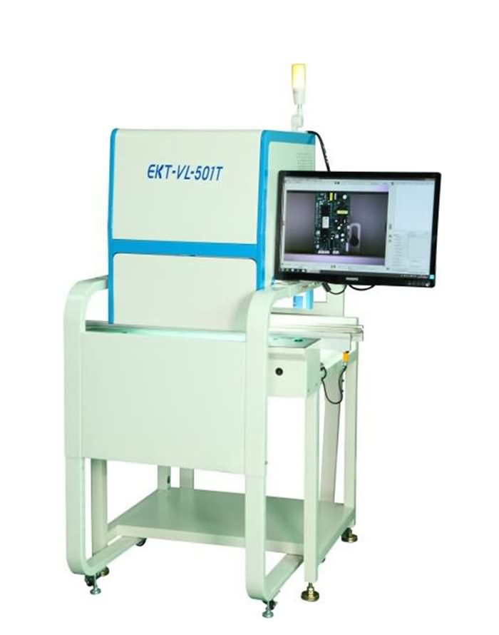
Best SMD AOI Machine - High Resolution SMT AOI Machine,SMD Inspection System for PCBA – Ektion
Best SMD AOI Machine - High Resolution SMT AOI Machine,SMD Inspection System for PCBA – Ektion Detail:
1 Introduction
In the fierce bai market competition, manufacturers of electronic products must ensure the quality of their products. In order to ensure the quality of products, it is particularly important to monitor the quality of semi-finished or finished products in each production link during the product manufacturing process. Assembling technology (SMT) used in the printed circuit board circuit pattern refinement, SMD components miniaturization and SMT components high-density assembly, rapid assembly development trend, the use of visual inspection or manual optical inspection methods can no longer adapt, automatic optics As a technical means of quality inspection, inspection (AOI) technology has become a general trend.
2 AOI working principle
There are many forms of applying AOI technology in SMT, but the basic principle is the same (as shown in Figure 1), that is, the image of the measured object is obtained by optical means, and the illumination image of the detected object is usually obtained through a sensor (camera) and Digitization, and then using a certain method to compare, analyze, inspect and judge, is equivalent to automatic and intelligent manual visual inspection.
2.1 Analysis algorithm
Different AOI software and hardware designs have their own characteristics. In general, their analysis and judgment algorithms can be divided into two types, namely design rule check (DRC) and pattern recognition check.
(1) The DRC method detects graphics according to some given rules. For example, all connections should be based on solder joints, and all lead widths and intervals should not be less than a specified value, etc. to check the PCB circuit pattern. Figure 2 is a solder paste bridging detection image based on this method. After extracting the digital image of the solder paste on the PCB, it is judged whether it is a bridging based on the solder paste shape in the pad spacing area. The measured solder paste shape exceeds the preset warning line and is recognized as a bridge[1]. The DRC method can algorithmically ensure the correctness of the inspected graphics. The corresponding AOI system is easy to manufacture and the algorithm logic is easy. Realizes the characteristics of high-speed processing, small amount of program editing, and small space occupied by data, but this method has poor ability to determine the boundary, and it is often necessary to design a specific method to determine the boundary position.
(2) The graphic recognition method is to compare the digital graphics stored in the AOI system with the experimental test images to obtain the test results. For example, when testing PCB circuits, first establish a test file (standard) according to a good PCB or computer-aided design model The digitized image) is compared with the inspection file (the actual digitized image). Figure 3 shows the quality inspection of the assembled PCB using this principle. The inspection accuracy of this method depends on the standard image, the resolution and the inspection program used. High detection accuracy, but it has the characteristics of large amount of collected data and high requirements for real-time data processing. Because the graphic recognition method uses design data to replace the design principles in DRC, it has obvious advantages in use.
2.2 Image recognition
(1) Image analysis technology. With the rapid development of computers, there are currently many mature image analysis technologies, including template matching (or automatic comparison), edge detection, feature extraction (binary image), gray-scale histogram Method, Fourier analysis method, optical feature recognition method, etc., each technology has advantages and limitations. The template comparison method obtains an image of an object, such as a chip capacitor or QFP, and uses the information to generate a rigid pixel-based template. In the vicinity of the detection position, the sensor finds the same object and evaluates all points in the relevant area After that, find the position with the smallest difference between the template and the image and stop searching. The system generates this template for each object to be inspected, and establishes an inspection program for the entire board by using the corresponding modules in different positions to check all requirements Components.
Since the component detection image rarely matches the template exactly, the template uses a certain amount of allowable error to confirm the match. If the template is too rigid, it may cause “false positives” for the component; if the template is loose enough to accept a large range of possible variables, It can also cause false alarms.
(2) Algorithms. Several popular image analysis technologies are combined in a “prescription”. It is hoped that an algorithm is particularly suitable for special component types. On a complex board with many components, many different algorithms may be formed, requiring engineers to change or Do a lot of reprogramming when adjusting. For example, when a supplier modifies a standard component, the algorithm of the component may need to be adjusted. When new changes occur, the user must adjust or “reverse” the algorithm to accommodate all possible changes, such as an 0805 chip capacitor. It can be classified as having a certain size and rectangular shape, with two bright sides enclosing a darker area, and then the appearance of this simple external component may vary greatly. Traditional, algorithm-based AOI methods are often too strict to be impossible With reasonable changes in contrast, size, shape, and shading, even unimportant components may be difficult to find and inspect reliably, resulting in “false rejections” where components cannot be found by the system. In addition, due to the small difference between acceptable and unacceptable images, the algorithm cannot be distinguished, causing “error reception”, and real defects cannot be found. In order to solve some problems, users must have appropriate knowledge in the field of image analysis, followed by traditional The AOI must be reprogrammed continuously and extensively, and the AOI method must be adjusted to accommodate reasonable changes. When designing a new version or optimizing an inspection program, it may take 1-2 days or even a few weeks to make minor changes.
(3) Statistical modeling technology. In order to overcome the shortcomings of traditional image processing methods, AOI adopts self-adjusting software technology. Its design separates users from the complexity of the algorithm. By displaying a series of examples to be identified as objects, AOI uses a mathematical technique, namely Statistical shape modeling technology (SAM) automatically calculates how to recognize reasonable image changes. Unlike algorithms based on algorithms, SAM uses self-adjusting, knowledge-based software to calculate variables. This can reduce programming time, eliminate daily adjustments, and the false alarm rate is 10-20 times lower than existing AOI methods.
(4) Flexible technology. Traditional AOI systems mainly rely on identifying the edges of components to achieve accurate and repeatable measurements. Once the edges are found, the symmetry models of these edges are usually used to generate the coordinates of the components on the board surface, but it is difficult to use visual technology. Finding the edge, because the edge of the component is not a completely straight line, attempts to match this edge with a straight line are problematic. In addition, the edge tends to be a black area on a black background. Accurate confirmation will produce pixel noise variables. Because the pixels cannot be small enough, it is easy to produce some pixel division effects. Based on the method of edge recognition, a good vision system often produces repeatability with a standard deviation of about 1-/10 pixels, and SAM technology can provide repeatable components with a standard deviation of 1/20 pixels. The total variable of the component position is less than 3/10 of each pixel, so when matching to 3 components, the accuracy and repeatability should be improved. When checking a specific component type, SAM is inherently flexible. When matching a legal component with a very different shape, it will move on the x and y axes in an attempt to achieve the best fit through position adjustment. When the SAM model matches the components, only those shapes that can actually occur, do not compromise the positions of x and y. For example, some allowable component color variables are caused by shadowing or excessive exposure of adjacent larger components. Traditional The algorithm is impossible to accept, but because SAM calculates the allowable image changes, users can accept it without relying on a large number of programmed algorithms or a library of algorithms supplied by suppliers.
(5) Stereo vision imaging technology. The traditional AOI system cannot fully accept the PCB shape, which is due to the natural three-dimensional change caused by local bending. The existing AOI system usually uses a telecentric lens to remove the parallax and perspective effects from the optics, because the perspective effect on the height is removed. The objects on the edges appear to be on the same plane as the objects in the middle. This eliminates optical parallax errors, but the measurement between points that should follow the arc of the board surface becomes a straight line distance across the plane chord, causing important measurement errors and automatically removing valuable information about the board surface shape.
By combining the SAM technology with the stereo vision arrangement of two rows of cameras, this AOI system can measure and accept the height of the object and the surface, and the result is a straight PCB mathematically. The camera at a certain angle provides two perspectives of the object. Calculate the height graphics of the PCB and the three-dimensional surface topology graphics. The precise position of any component on the board is also calculated by counting its height on the board surface. When working, the AOI equipment uses a standard board conveyor belt to move the PCB through the camera according to the scale. Camera arrangement, the stereo image pair of the image is arranged to form a photograph mosaic, and then the photograph mosaic is synthesized and flattened or analyzed in real time. The combination of SAM technology and stereo vision imaging technology has high accuracy and repeatability, and it is available For important component confirmation and PCB inspection.
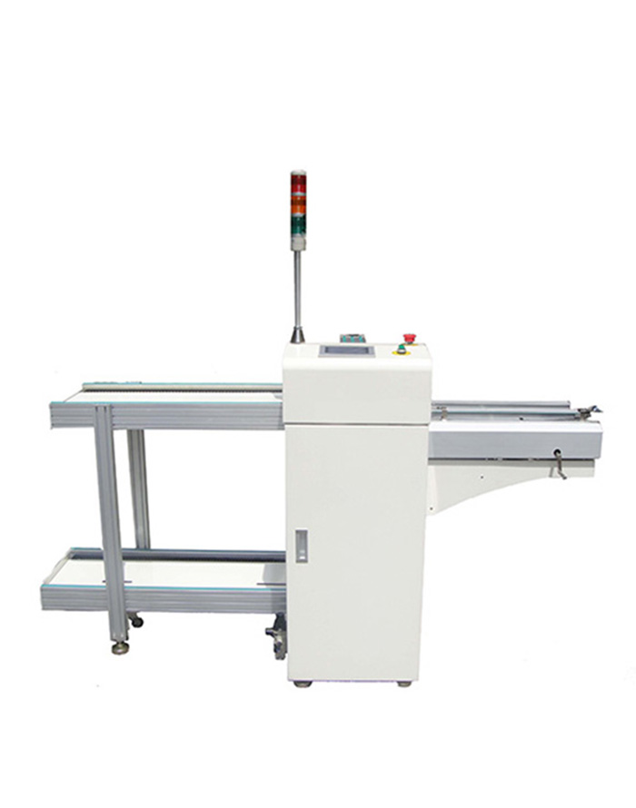
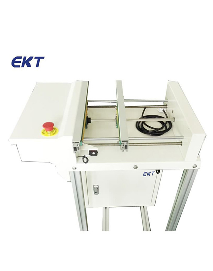
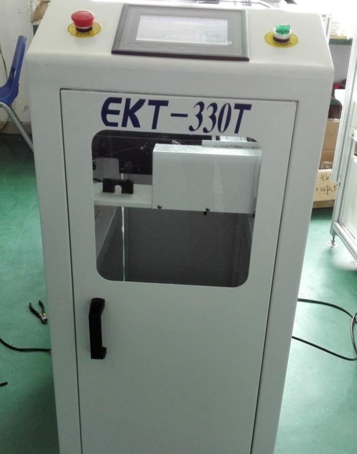
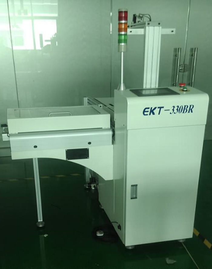
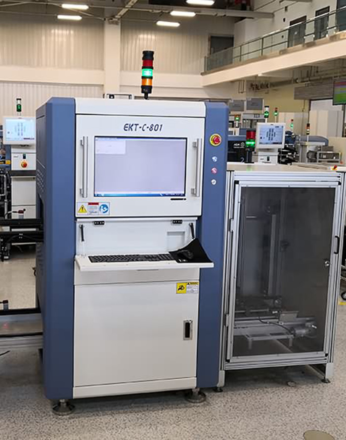
Product detail pictures:
Related Product Guide:
We always stick to the principle "Quality First, Prestige Supreme". We are fully committed to providing our clients with competitively priced quality products, prompt delivery and professional service for Best SMD AOI Machine - High Resolution SMT AOI Machine,SMD Inspection System for PCBA – Ektion , The product will supply to all over the world, such as: Guyana , Algeria , Vancouver , We will continue to devote ourselves to market & product development and build a well-knit service to our customer to create a more prosperous future. Please contact us today to find out how we can work together.
The factory has advanced equipment, experienced staffs and good management level, so product quality had assurance, this cooperation is very relaxed and happy!